Multimeter to the Rescue!
By Tom Hale
Waking from a sound sleep to the sound of an alarm is a pretty common occurrence on Monday mornings. I groggily looked over at the bedside clock. It wasn’t there! I snapped fully awake! I was not at home getting up for work: I was on my boat with an alarm ringing. It was not the usual anchor alarm. It was not one of the electronic instruments going off. It was not the smoke/CO detector. It was a new sound, one I had not heard before.
What was making that infernal racket?
The electrical panel looked to be in order. Battery voltage was normal. I opened the engine hatch, and there it was: water filled the bilge. Neither of the two bilge pumps was running.
I checked the main bilge pump switch: it was on. I checked the backup pump: its light was off. I activated that switch: the light came on, and so did the 2000-gph backup pump. That was a relief!
I looked carefully at the primary pump. Its float switch was pointing up, so it should have been pumping. I switched it to the “manual” position, but still nothing happened.
I had two issues to solve here. First, where did the water come from? Second, why was the pump not running?
The water looked milky, so I checked the shower sump. Full! That pump was not working either. The water from our showers had spilled into the bilge, and at some point in the night the boat rocked enough to tip the float on the high-water bilge alarm.
Whew. At least we weren’t sinking! The backup bilge pump made short work of the water, and I thought about going back to bed, but I couldn’t sleep knowing that two pumps—the sump and the bilge—had failed.
I unsnapped the bilge pump’s float switch from its base and shook it. That was a reflex thing; it didn’t do anything. I unsnapped the pump from its base. The impeller moved when I spun it with the tip of a screwdriver. It seemed to spin okay, which suggested that the problem was not mechanical. Clearly it was time to break out the multimeter to see if the pump was getting electricity.
In boating, electrical problems are common. After all, marine electrical systems live in a corrosive, salt environment with heat, cold and vibration, any of which could deliver a knockout blow to the flow of electricity. A multimeter can help in the diagnosis of most common problems. For many boaters, knowing when and how to use a multimeter is limited. It helps to brush up on basic electrical theory first.
Bilge pumps run on 12-Volt DC power from your battery. A fully charged 12-Volt battery measures ~12.6 volts, a dead battery is about 11.75 volts.
A battery charger will “float” a wet cell lead acid battery at ~13.6 volts after recharging it.
When I tested it, the shower sump did operate in the manual mode, indicating that the pump itself was okay, but its float switch was bad. I replaced the float, and voila, the shower sump emptied and the pump shut itself off. One problem solved.
The primary bilge pump was a more complicated problem. It was not pumping in either automatic or manual mode. In this situation, the first thing to check is the power supply to make sure electricity is available. I checked the fuse, which was intact. Power should have been getting to the pump.

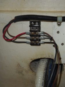
Picture 1 shows the electrical distribution block for the pump. The red wire on the left is the positive lead from the switch in the “manual” position. The brown wire is the positive power lead to the float switch, and the black wire is the negative ground wire leading back to the battery. On the right-hand side, the brown wire is the positive wire to power the pump. The gray wires are the float switch wires and the black wire is the negative wire from the pump. (Note: for simplicity I unfastened the electrical block and put it up on the floor so it is easier to demonstrate the trouble and troubleshooting)
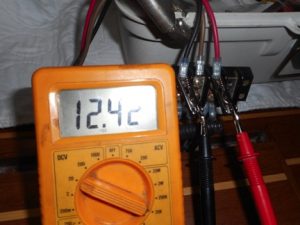
First, I checked to see if there was power to the pump. I set my multimeter to the DC Voltage scale and clipped the black lead to the pump’s negative lead (black) and the red lead to the pump’s positive (red). The multimeter showed no voltage between the red (+) and the (-) at the pump connections when the manual switch was turned on. There should have been full battery power.


In my years of working on marine electrical systems, I’ve noticed that problems seem to occur in the ground (negative) side of the circuit. I connected my multimeter’s leads to red wire and to the battery’s negative terminal. Sure enough, it showed full voltage on the power supply, indicating that voltage was at the terminal block, but current was not able to flow through the pump’s negative wire. (Picture 2 and 2B)

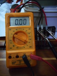
I set the multimeter to the resistance (Ohm) scale to determine whether or not electricity was actually able to flow through the wire. Next, I connected the meter leads to the battery negative bus and to the black conductor. The meter read 1.0, indicating infinite resistance. (Picture 2c) That meant the line was broken. Damn.

At 3 o’clock in the morning, trying to trace this wire through the wiring harness was more than I was up for. Instead I ran a new wire from the main negative bus to the pump distribution block. When I was done, the multimeter read 0.00 resistance in the ground wire. (Picture 2d) Perfect!
I turned on the pump, and it started pumping water out of the boat. I switched it over to the automatic position, and the pump continued until the float shut it off. Just to be sure I lifted the float with my finger: pump on. I dropped it: pump off. Picture 3.
To recap: Using our multimeter set on the DC volt scale we were able to determine when we had voltage available and when we did not. Setting the meter to the Ohm scale, we could tell whether or not a wire was able to conduct.
Some two hours after the alarm sounded, I crawled back in my bunk. Satisfied that the bilge pump systems were fully operational I drifted off to sleep. Three hours later, the morning alarm sounded. I did not take it well. When I finally decide to get up, I’ll have to find the damn clock and see if I can fix that, too.

